
The ESP32-CAM is a convenient little camera module with a lot of built-in power, and you can turn one into an inconspicuous spy camera to hide in any room. There's only one issue: it does omit a USB port. That makes it a little harder to program, but with an ESP32-based board, FTDI programmer, and some jumper wires, you'll have a programmed ESP32 Wi-Fi spy camera in no time.
To build the program for the spy camera, which includes facial detection and recognition, we'll be using Arduino IDE, and to flash the program over to the ESP32-CAM, we'll need the FTDI programmer and either male-to-mail jumper wires and a breadboard or female-to-female jumpers. If you want to power the board independently after it's been programmed, you can add a LiPo battery board meant for a D1 mini, which will let you add a rechargeable LiPo battery.
Parts Needed
This is the basic stuff you need to continue with this project:
- ESP32-CAM Camera Module with FTDI USB to TTL Serial Converter ($12.89)
- D1 Mini Battery Shield with Charging Module ($8.99)
- 3.7 V 500 mAh LiPo Battery ($9.20)
- Solderless Breadboard ($8.99)
- Jumper Wires ($5.99)
- Mini-USB Cable ($6.81)
- Arduino IDE Software (free)
Note that the battery required can be a different size if needed.
Step 1: Set Up the Camera in Arduino IDE
In the Arduino IDE, navigate to "Arduino" or "File" in the menu bar, select "Preferences," then click the window icon next to "Additional Boards Manager URLs." On a separate line, add the following URL, then choose "OK" and "OK" again.
https://dl.espressif.com/dl/package_esp32_index.jsonNext, in the menu bar, go to "Tools," then "Board," and then "Boards Manager." In the search field, type "esp32," then install the latest version of "esp32 by Espressif Systems."
- Other Projects That Use This Board: Enable Offline Chat Communications Over Wi-Fi with an ESP32
Step 2: Open the Default Camera Sketch
Go to "Tools" again in the menu bar, choose "Board," then select "AI Thinker ESP32-CAM" under the "ESP32 Arduino" section. With that board selected, go to File –> Examples –> ESP32 –> Camera –> CameraWebServer. This will open the sketch, and you'll see the following code.
#include "esp_camera.h"
#include <WiFi.h>

//
// WARNING!!! PSRAM IC required for UXGA resolution and high JPEG quality
//            Ensure ESP32 Wrover Module or other board with PSRAM is selected
//            Partial images will be transmitted if image exceeds buffer size
//

// Select camera model
#define CAMERA_MODEL_WROVER_KIT // Has PSRAM
//#define CAMERA_MODEL_ESP_EYE // Has PSRAM
//#define CAMERA_MODEL_M5STACK_PSRAM // Has PSRAM
//#define CAMERA_MODEL_M5STACK_V2_PSRAM // M5Camera version B Has PSRAM
//#define CAMERA_MODEL_M5STACK_WIDE // Has PSRAM
//#define CAMERA_MODEL_M5STACK_ESP32CAM // No PSRAM
//#define CAMERA_MODEL_AI_THINKER // Has PSRAM
//#define CAMERA_MODEL_TTGO_T_JOURNAL // No PSRAM

#include "camera_pins.h"

const char* ssid = "*********";
const char* password = "*********";

void startCameraServer();

void setup() {
  Serial.begin(115200);
  Serial.setDebugOutput(true);
  Serial.println();

  camera_config_t config;
  config.ledc_channel = LEDC_CHANNEL_0;
  config.ledc_timer = LEDC_TIMER_0;
  config.pin_d0 = Y2_GPIO_NUM;
  config.pin_d1 = Y3_GPIO_NUM;
  config.pin_d2 = Y4_GPIO_NUM;
  config.pin_d3 = Y5_GPIO_NUM;
  config.pin_d4 = Y6_GPIO_NUM;
  config.pin_d5 = Y7_GPIO_NUM;
  config.pin_d6 = Y8_GPIO_NUM;
  config.pin_d7 = Y9_GPIO_NUM;
  config.pin_xclk = XCLK_GPIO_NUM;
  config.pin_pclk = PCLK_GPIO_NUM;
  config.pin_vsync = VSYNC_GPIO_NUM;
  config.pin_href = HREF_GPIO_NUM;
  config.pin_sscb_sda = SIOD_GPIO_NUM;
  config.pin_sscb_scl = SIOC_GPIO_NUM;
  config.pin_pwdn = PWDN_GPIO_NUM;
  config.pin_reset = RESET_GPIO_NUM;
  config.xclk_freq_hz = 20000000;
  config.pixel_format = PIXFORMAT_JPEG;

  // if PSRAM IC present, init with UXGA resolution and higher JPEG quality
  //                      for larger pre-allocated frame buffer.
  if(psramFound()){
    config.frame_size = FRAMESIZE_UXGA;
    config.jpeg_quality = 10;
    config.fb_count = 2;
  } else {
    config.frame_size = FRAMESIZE_SVGA;
    config.jpeg_quality = 12;
    config.fb_count = 1;
  }

#if defined(CAMERA_MODEL_ESP_EYE)
  pinMode(13, INPUT_PULLUP);
  pinMode(14, INPUT_PULLUP);
#endif

  // camera init
  esp_err_t err = esp_camera_init(&config);
  if (err != ESP_OK) {
    Serial.printf("Camera init failed with error 0x%x", err);
    return;
  }

  sensor_t * s = esp_camera_sensor_get();
  // initial sensors are flipped vertically and colors are a bit saturated
  if (s->id.PID == OV3660_PID) {
    s->set_vflip(s, 1); // flip it back
    s->set_brightness(s, 1); // up the brightness just a bit
    s->set_saturation(s, -2); // lower the saturation
  }
  // drop down frame size for higher initial frame rate
  s->set_framesize(s, FRAMESIZE_QVGA);

#if defined(CAMERA_MODEL_M5STACK_WIDE) || defined(CAMERA_MODEL_M5STACK_ESP32CAM)
  s->set_vflip(s, 1);
  s->set_hmirror(s, 1);
#endif

  WiFi.begin(ssid, password);

  while (WiFi.status() != WL_CONNECTED) {
    delay(500);
    Serial.print(".");
  }
  Serial.println("");
  Serial.println("WiFi connected");

  startCameraServer();

  Serial.print("Camera Ready! Use 'http://");
  Serial.print(WiFi.localIP());
  Serial.println("' to connect");
}

void loop() {
  // put your main code here, to run repeatedly:
  delay(10000);
}
Step 3: Tweak the Example Sketch's Code
In the default CameraWebServer sketch, we need to make sure our AI Thinker board is selected and not another board. Right now, the following board will not be commented out:
#define CAMERA_MODEL_WROVER_KIT // Has PSRAMAnd you need to add // to the beginning of that, then remove the // from the beginning of this line:
//#define CAMERA_MODEL_AI_THINKER // Has PSRAMSo that section in the code should look like this now:
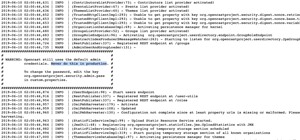
// Select camera model
//#define CAMERA_MODEL_WROVER_KIT // Has PSRAM
//#define CAMERA_MODEL_ESP_EYE // Has PSRAM
//#define CAMERA_MODEL_M5STACK_PSRAM // Has PSRAM
//#define CAMERA_MODEL_M5STACK_V2_PSRAM // M5Camera version B Has PSRAM
//#define CAMERA_MODEL_M5STACK_WIDE // Has PSRAM
//#define CAMERA_MODEL_M5STACK_ESP32CAM // No PSRAM
#define CAMERA_MODEL_AI_THINKER // Has PSRAM
//#define CAMERA_MODEL_TTGO_T_JOURNAL // No PSRAM
Then, we need to put in the SSID name and password for the Wi-Fi network that we want to connect the spy camera to. Look for these two lines, then replace the asterisks with your Wi-Fi network's name and password.
const char* ssid = "*********";
const char* password = "*********";
That's it for customizing the sketch. Hit the compile button to compile it, then you'll be ready to flash your ESP32-CAM with the program.
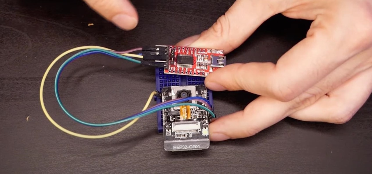
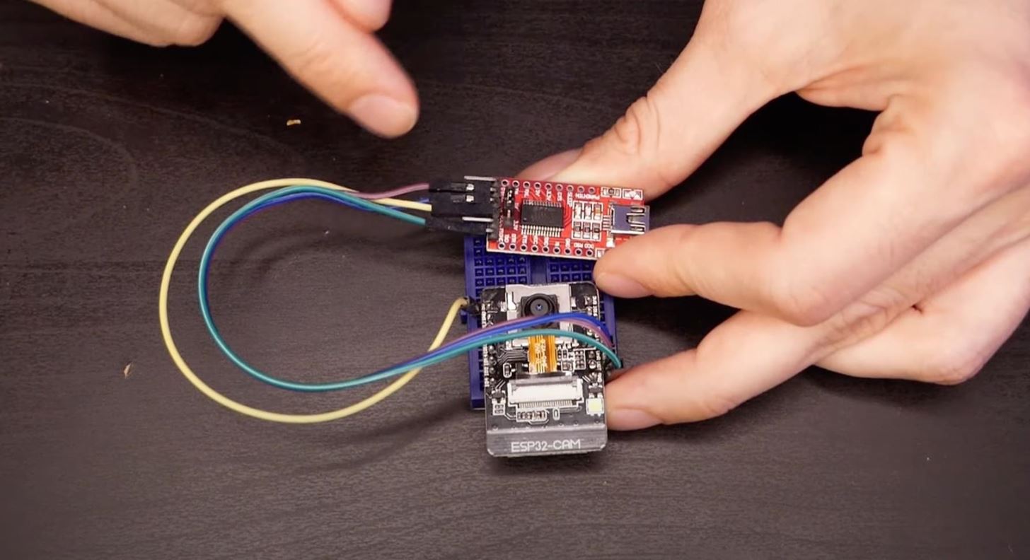
Step 4: Wire Up Your ESP32-CAM
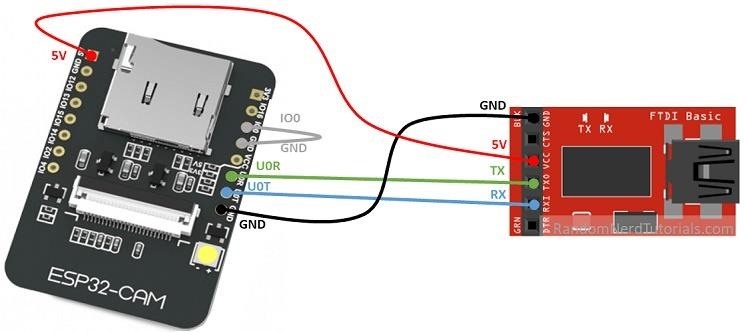
With your FTDI programmer and ESP32-CAM module, use jumper wires with or without a breadboard to connect the FTDI programmer and ESP32-CAM module together.
- Connect GND on the FTDI to GND (by U0T) on the ESP32-CAM.
- Connect 5V on the FTDI to 5V on the ESP32-CAM.
- Connect TX on the FTDI to U03 on the ESP32-CAM.
- Connect RX on the FTDI to U0T on the ESP32-CAM.
- Connect I00 on the ESP32-CAM to GND right next to it.
That last one is too short the CAM module so that it can be put into programming mode.
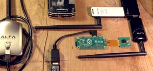
This is what it should look like when done:
Step 5: Upload the Sketch to Your ESP32-CAM
Once all the jumpers are in place, you can connect a Mini-USB cable to it with the regular USB end to your computer, then upload the sketch.
Locate the port your ESP32-CAM is connected to in the Arduino IDE. First, go to "Tools," choose "Board," then select "AI Thinker ESP32-CAM" under the "ESP32 Arduino" section if you haven't already done so for some reason (you should have in Step 2).
Next, go to "Tools," select "Port," then change it to the correct one if it hasn't already been selected automatically. Be extra cautious that you've selected the right port for the ESP32-CAM, as you will not want to overwrite any other devices.
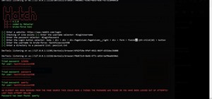
To flash over the Wi-Fi sketch to your ESP32-CAM, click on the upload button (the right arrow in the top left). You'll see a bunch of stuff happen. Once the red text appears on the screen, you know it's actually flashing it over. When it's done, you can open up the Serial Monitor with Control-Shift-M to make sure there were no crazy errors or brownouts and to look for reboots.
After flashing the sketch to the ESP32-CAM, look for the IP address of the board in the Serial Monitor. You'll need this later.
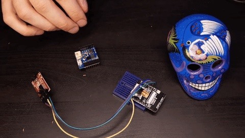
Step 6: Find a Power Source for Your ESP32-CAM
Now that your ESP32-CAM is programmed, you can disconnect the FTDI programmer; you'll only need that again if you need to update the code on your spy camera later. You could also connect a constant power source to the FTDI programmer when still connected to the ESP32-CAM if you want to power the camera up that way, but since we want it to be a spy camera, a battery would be much better.
Disconnect the ESP32-CAM from the breadboard, then connect it to a D1 Mini Battery Shield, which will let us power the spy camera with a small LiPo battery. When connecting them, make sure you have the 5V pins on both lined up correctly. Then, connect a lithium-ion polymer battery to the Battery Shield using its two-pin JST-PH connector. I'm using a 3.7-volt 500 mAh battery.
Step 7: Connect to Your Spy Camera's Interface
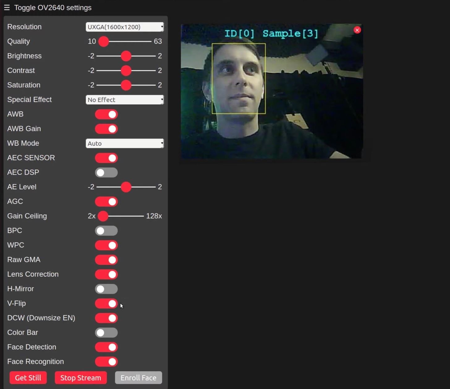
In a browser window, open the IP address for the ESP32-CAM that you found earlier on the same Wi-Fi network. This will give you access to the spy camera's settings. You can change the resolution, video quality, brightness, contrast, and saturation until you get the image you want, as well as add special effects and adjust other options.
At the bottom of the menu is where you'll see the "Face Detection" and "Face Recognition" options, which you can toggle on. Right now, it only works with resolutions of 400 x 296 and lower.
Hit "Start Stream" at the bottom to view the video stream. If you have only facial detection on, you should see a box around anyone's head to know that it's working. With facial recognition on, it will do the same but also name the face, which will be an intruder at first. You can click the "Enroll Face" button to enroll it as a non-intruder.
Hide This Thing Wherever You Want
These boards can get pretty hot, so depending on your battery and how long you're running the camera, it may not work or will shut down. If that happens, look into getting a proper heat sink to dissipate the heat and keep things cooler. The more stuff you add to the spy camera, the harder it will be to hide it somewhere inconspicuous, so keep that in mind.
Just updated your iPhone? You'll find new emoji, enhanced security, podcast transcripts, Apple Cash virtual numbers, and other useful features. There are even new additions hidden within Safari. Find out what's new and changed on your iPhone with the iOS 17.4 update.


1 Comment
Quick note: on my board, if I used the ground pin indicated in the diagram here I got a solid LED from the board and couldn't upload. What ended up fixing it was moving the ground pin from the original to the ground pin next to the 5v pin. It might have to do with how my board is labeled GND/R at the original pin.
Share Your Thoughts