

With portable devices being a necessity in modern everyday life, they may be subject to overuse, improper charging, or normal wear and tear. For those people who carry around their smartphone or iPod with them all of the time, how many times have you been out and about just to have your portable device die on you?
Maybe the battery isn't as good as it used to be. Maybe you didn't feel like lugging a laptop around just to be a "spare battery" for your device. It doesn't matter. You need juice for your device and you don't have it. Today, Null Byte is going to show you a cool and moderately cheap method to make a portable charger that will even work on iOS devices.
The best part? It's powered by batteries.
Requirements
All materials can be purchased from a convenient little DIY kit from Adafruit. You could also buy the parts separate for cheap. Here's some files you may need, including schematics.
Included in the MintyBoost Kit
- 1 x IC1 MAX756 with Socket
- 2 x C2, C3 Power Supply Capacitor
- 2 x C1, C4 Bypass Capacitor
- 2 x R4, R5 10k .25W Resistor
- 1 x D1 Schottky Diode
- 1 x L1 Power Inductor
- 1 x X1 USB Female Jack
- 1 x Battery Holder
- 1 x PCB (printed circuit board)
You'll Also Need
- Soldering Iron
- 60/40 solder
- 2 x AA batteries
- Wire cutters
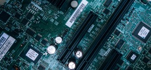
Step 1: Soldering Parts
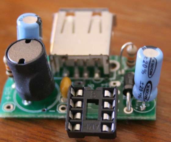
Heat up your soldering iron and get ready to put everything on the PCB, starting with the capacitor.
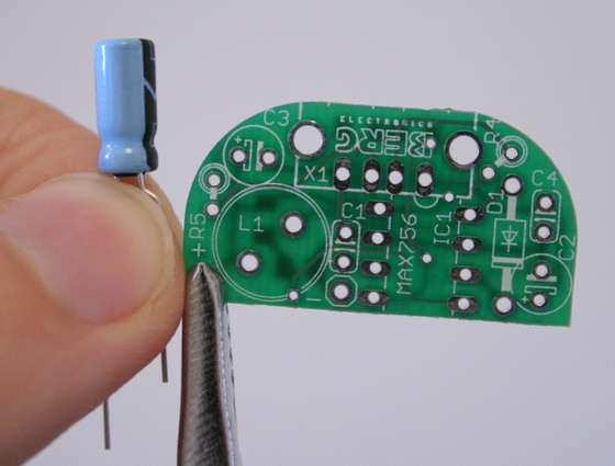
The capacitors have a stripe that needs to be in the same direction as the stripe on the PCB. You can also follow the + on the board. The longer leg of the capacitor is positive.
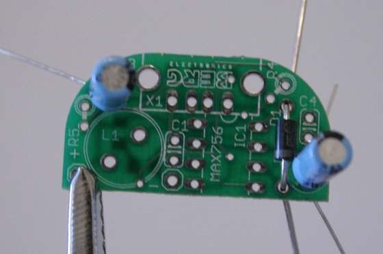
Put all these parts through their proper holes, and bend the wires around the back a little so they don't fall out when you turn the PCB over.
Solder them in and snip the excess tails off.
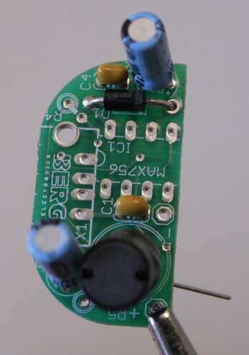
Rinse and repeat.
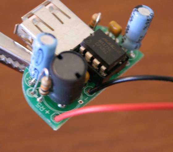
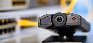
Step 2: Soldering the Board
Solder the USB port on the board above where it says "BERG". Use common sense. Think "square peg in a round hole" and you'll get it. Solder on your IC socket and power cables. You'll be good to go!
And...
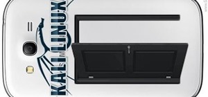
Step 3: Make It Work with iOS Devices
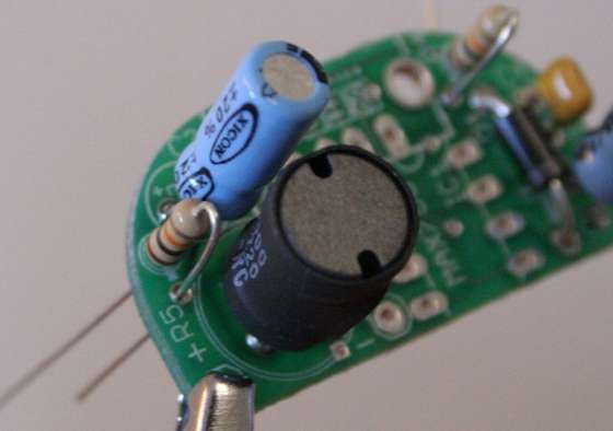
If you want to be able to charge newer devices, like iPods, simply reverse the resistor like so:
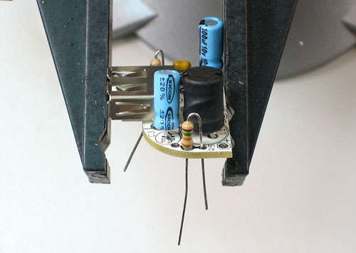
Have fun with your mobile juice and keep on gaming with your iPhone!
Want more Null Byte?
Just updated your iPhone? You'll find new emoji, enhanced security, podcast transcripts, Apple Cash virtual numbers, and other useful features. There are even new additions hidden within Safari. Find out what's new and changed on your iPhone with the iOS 17.4 update.


9 Comments
There are a few solar charged ones from BrownDogGadgets.com that you can either but made or a kit. When I buy a kit, I will make a tutorial.
Reverse the resistor? There is no + or - on a resistor, so what does that mean?
that's what i though too, the i realized, they are different ohms.
Good idea. But I'm not specially for Electrical.. :D
Resistors aren't polarized. The way the stripes face doesn't affect anything.
There's a typo, the IC should be MAX756, NOT the MAX746, which is a step down controller
so guys whats the thing cost anyway?
Dear sir,
can you send me circuit diagram of it
Can any one tell me the diagram of this circuit
Share Your Thoughts