
Microcontrollers like ESP8266-based boards have built-in Wi-Fi, and that's really cool, but what's even cooler is that certain pro models of the D1 Mini also have a port where you can connect a directional antenna. This can give you exceptional range, but if you were to just plug one in after opening the package, it most likely wouldn't work.
The problem, as Glytch covered in a Hak5 video last year, is that there's a tiny zero-ohm resistor on the board that's connecting the built-in antenna to the chip, but it needs to connect to the external directional antenna. To do so, that tiny resistor needs to be changed to a different pad that connects it to the breakout adapter. So a little bit of surface mount soldering is needed to fix the issue.
Things You'll Need
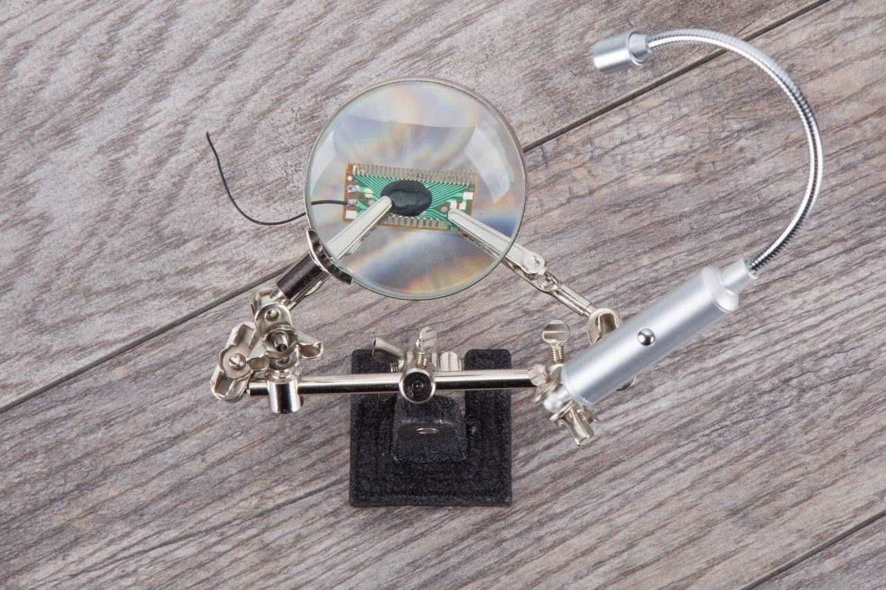
A couple of things are needed to connect a directional antenna to a D1 Mini successfully. First, a soldering station, also known as a helping hands stand, is needed to hold onto the D1 Mini so that you don't burn yourself in the process or lose anything.
Soldering stations can be cheap or a little pricy, and some come with a magnifying glass and light, and some do not. You'll definitely need a magnifying glass for this job, and any of the ones below will work. If you already have an LED light, Neiko's is a solid inexpensive option. Newacalox's stand has lots of alligator clips and a magnifier with LEDs that have three different color temperatures but is pricier.
- Neiko 2-Clip Stand with 2X Magnifying Glass ($12)
- Hi-Spec 2-Clip Stand with 2X Magnifying Lens with LEDs ($19.99)
- Ram-Pro 2-Clip Stand with 3X Magnifier & LED Flex Light ($14.99)
- Newacalox 5-Clip Stand with 3X Magnifying Glass with 3-Color LEDs ($40.99)
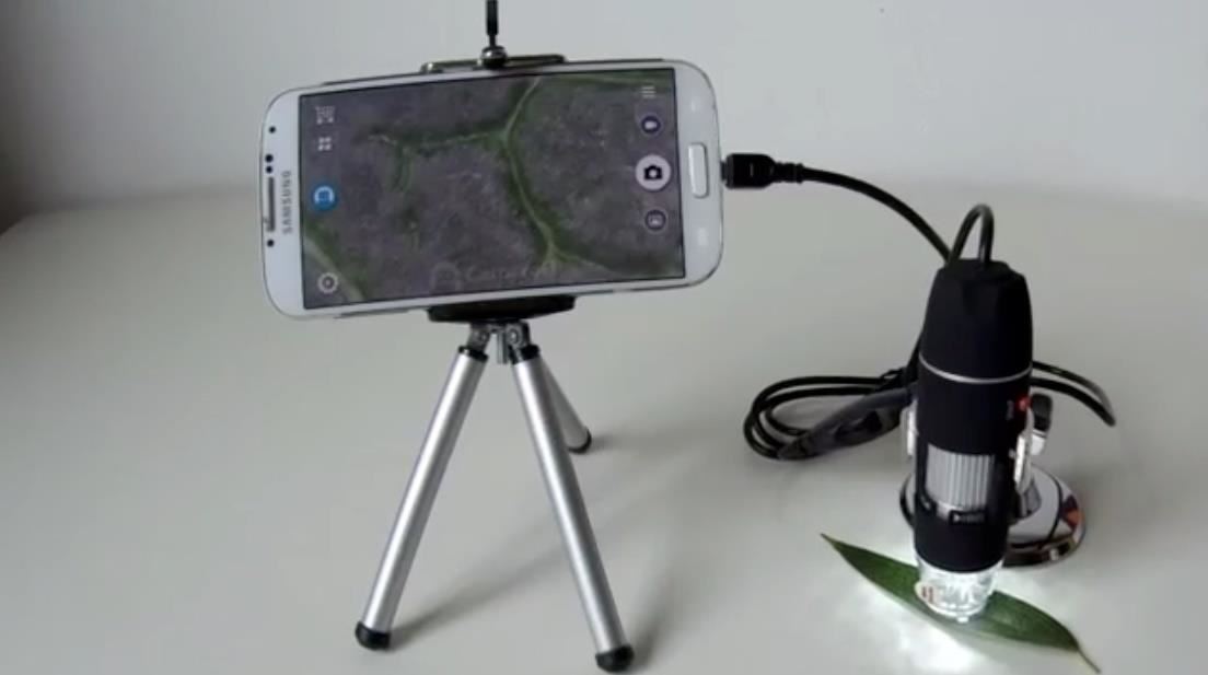
For many, the magnifying glass may not be powerful enough to see the components clearly on the board. If you think that'll be you, you could also get a digital microscope with a miniature camera so that you can display it on a computer monitor. I use a Jiusion 40–1,000x digital microscope, but there are others you could shop for.
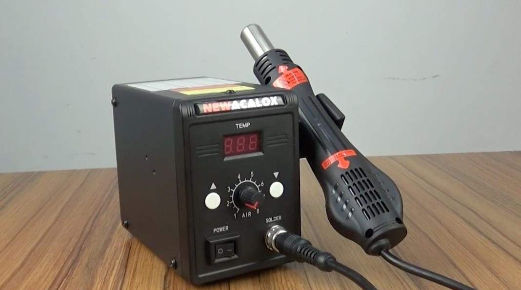
Second, a good pair of tweezers will help nudge the resister to the right spot. Third, a hot air rework station with a hot-air gun to heat the solder so that the part can be moved without burning the board. You could try using a soldering iron, but the part that needs moved tends to get stuck to the iron, so a hot-air gun makes it a little less difficult. The Newacalox hot air rework station that I used comes with a couple of tweezers too, and there's a newer version of it for the same price.
- Newacalox NEW-858D Hot Air Rework Station with Hot Air Gun ($49.99)
- Newacalox OLD-858D Hot Air Rework Station with Hot Air Gun ($49.99)
Next, you need an ESP8266-based D1 Mini Pro microcontroller that has a breakout adapter. This one from Reland Sung on Amazon has the cable and antenna connector needed. It also has an antenna, but it's not the directional antenna we will be connecting today.
The directional antenna I'm using is an Alpha brand panel antenna. Check out our antenna picking guide and directional antenna overview to learn more about directional antennas and the ones available.
- Alfa RP-SMA 7 dBi Panel Antenna ($10.99)
Step 1: Place the D1 Mini in Your Helping Hands
Before you do anything, clamp in your D1 Mini board with the alligator clips on the soldering stand. Make sure the board is positioned with the right side up. Get some lights on it to see and position the magnifying glass so you can see the smaller parts of the board easily. If you're having a hard time seeing the components on the board, you may need to get a digital microscope with more magnification.
Step 2: Locate the Zero-Ohm Resistor
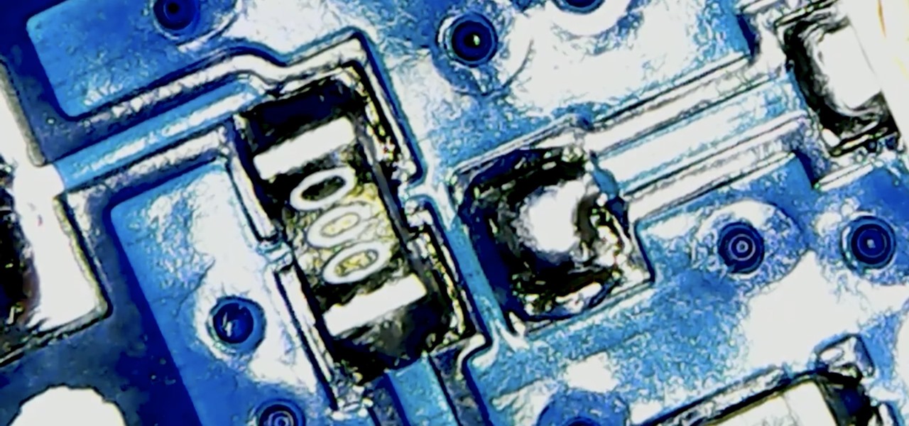
On your D1 Mini, find the zero-ohm resistor for the antenna. It should look like the one below. The resistor is soldered to the internal antenna on the left side, but it needs to be moved so that it's soldered to the empty pad on the right, which leads to the adapter port. As it is now, our external directional antenna would be completely cut off from the microcontroller when connected.
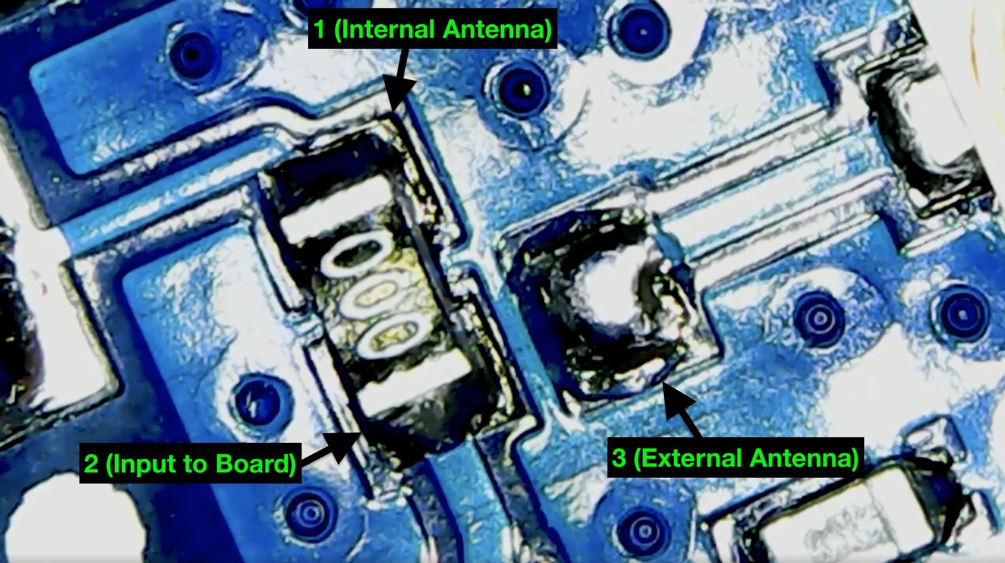
To fix it, we'll need to desolder the resistor from the internal antenna pad (1 in the picture above) and input pad (2 above) and resolder it to the input pad (2 above) and the external antenna pad (3 above).
Step 3: Heat Up Your Hot Air Gun
To move the resistor, get your hot air rework station ready to go and heated up. Use the knob to adjust the amount of air that flows through and the temperature buttons to get it up to the right temp. It's similar to a soldering iron where you'll only want to apply the necessary heat to the solder with the hot air gun. I set my gun to 290-degrees Celsius (554-degrees Fahrenheit).
Step 4: Heat the Solder & Remove the Resistor
When you pick up the gun, it should automatically start so that you can use the hot air to melt the solder. Point the hot air gun over the board to heat the solder at the resistor so that it's warm, but keep an eye on the board in the magnifying glass or microscope to make sure there is no burning happening.
Go back and forth to make sure you're heating all the solder under it, then get closer with the gun to apply some more direct heat to melt the solder. You'll notice that the flux will start to go a bit until the solder melts. Just make sure you're careful, as the hot air gun could actually blow away the resistor if you're applying too much air to it.
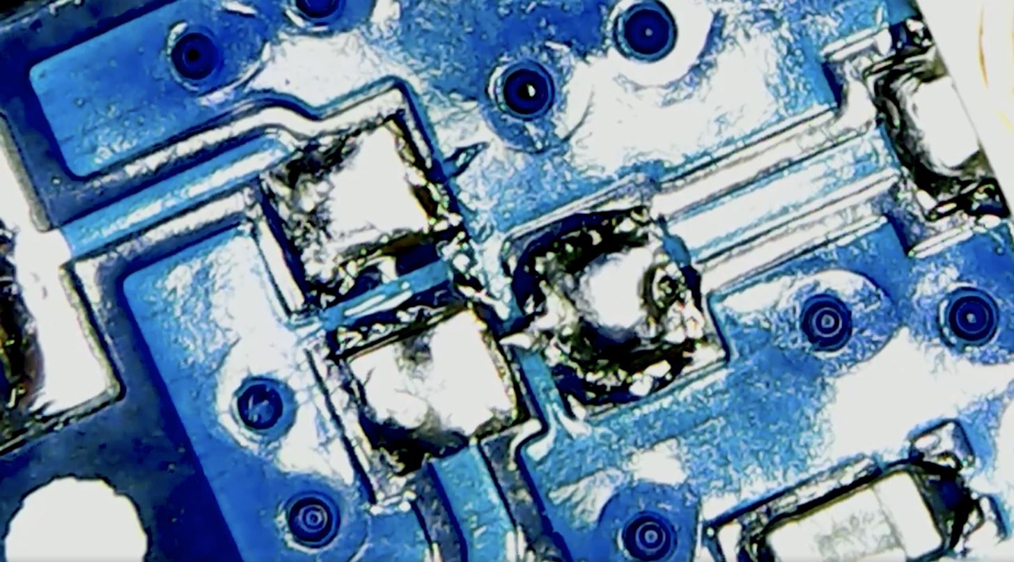
When it's melted enough, use a good pair of tweezers to pull the resistor from the pads gently. It's delicate work, so be very careful the resistor doesn't fly off the board where you'll never be able to find it.
Step 5: Replace the Resistor to Connect the External Antenna
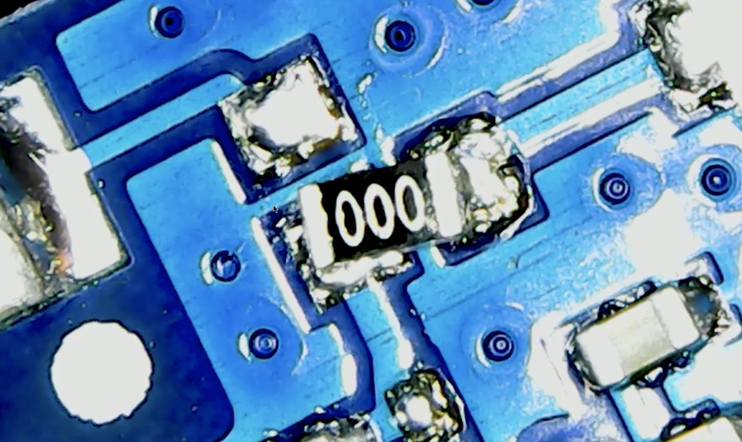
Now, keep applying heat to the solder to get the pads for the input and breakout adapter for the external antenna. Then, very carefully rest the resistor you pulled onto the correct pads. It doesn't have to be pretty, just as long as there's a good connection.
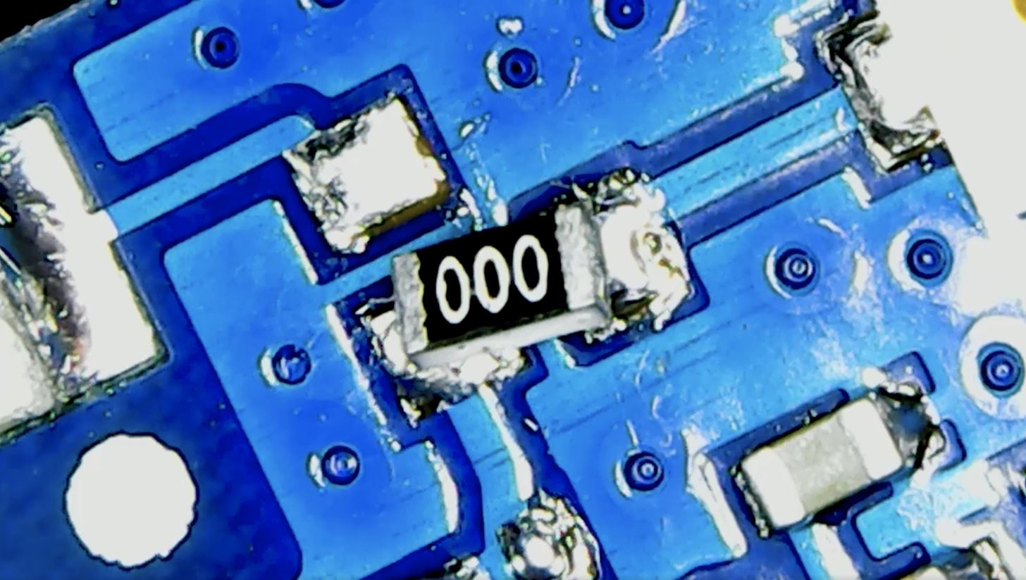
Step 6: Heat the Solder Joints Again to Create a Circuit
For good measure, heat the solder joints again to make sure there's a good connection. Then, let it dry a bit so that there's a solid lock on the pads. Once it dries, try moving it with the tweezers to make sure it's steady. If not, heat it again and position it better.
Step 7: Test Out Your Directional Antenna
Now it's time to test out the board and antenna. Attach the breakout cable to the board and your directional antenna to its adapter. Next, test your work by plugging the board into a Micro-USB cable to a power supply to create a hotspot with the board. If you haven't already, check out our guide on creating a D1 Mini test network for hacking to turn it into a hotspot you can connect to.
After plugging it into a power supply and creating a hotspot, use a computer with Wireshark on the other side of the room to detect whether or not there's a signal spike when moving the directional antenna back and forth. If it were an omnidirectional antenna, you would see a steady signal, but there should be a big spike when you point your directional antenna directly to the computer.
Exceptional Range
Adding a directional Wi-Fi antenna to a D1 Mini can give your project an exceptional range. If you were to make this modification on two separate ESP8266-based boards and put them a couple of miles apart, you would probably be able to get your devices to connect far beyond the traditional range you would expect for this little IoT board.
Just keep in mind that it's really easy to accidentally blow away the little zero-ohm resistor while fixing the board. So if you're using a hot air station that's not adjustable, make sure that you're doing the work very carefully, heating the board slowly, because it's really annoying to have this thing of flying off into nowhere land.
Just updated your iPhone? You'll find new emoji, enhanced security, podcast transcripts, Apple Cash virtual numbers, and other useful features. There are even new additions hidden within Safari. Find out what's new and changed on your iPhone with the iOS 17.4 update.


Be the First to Comment
Share Your Thoughts